 |
Spaceport Rocketry Association Premier rocketry organization serving the Florida Space Coast since 1973 |
| Gallery |
|
Motor Staging Information |
|
Motor staging is the use of more than one motor, each fired in sequence, and typically with each motor (stage) being discarded after it is used. Staging extends the thrust time which makes this technique especially effective for achieving higher altitudes.
|
|
Staging composite propellant motors is more complex than staging
black powder motors. Composite motors are more difficult to
ignite and they do not reach operating pressure (full thrust)
immediately. Several factors must be considered when staging
high power rocket motors. Starting with a two-stage kit is an
excellent way to begin. |
Public Missiles Ltd (PML)
Thunder -N- Lightning A typical two-stage design with sustainer two-event recovery. From left to right: nose cone, upper center section (main recovery system), lower center section (altimeter electronics bay and drogue recovery section), sustainer motor/fin section, interstage coupler (timer electronics bay) and booster motor/fin section (booster recovery system). The two sustainer center sections are secured together for flight. |
|
BOOSTER MOTORS The
purpose of the booster motor is to get the rocket off of the
pad, to achieve as much initial velocity as possible, and to
reach the final desired velocity if possible (without delving
into the aerodynamics, this will be just below the transonic
regime for subsonic flight). In general, a fast burning motor
will be the best choice. A
good rule-of-thumb for booster motor sizing is to have a rapid
thrust build-up to a minimum initial thrust to weight ratio of
5½. This is a typical thrust profile of a faster burning motor
and it is more critical than for single-stage rockets. The
higher the rocket velocity when it leaves the launch rod, the
straighter the flight will remain. Non-vertical flight is
exaggerated by staging, especially if there is any coast time
between booster burnout and sustainer ignition. If the booster motor has significant thrust until burnout the problem of sustainer motor ignition timing is simplified as discussed below. This again is typically achieved in faster burning motors. |
|
SUSTAINER MOTOR IGNITION TIMING
When to ignite the sustainer motor will depend on the booster
motor thrust curve, the velocity at booster motor burnout, and
by the type of booster-sustainer separation. Igniting the
sustainer motor too soon could throw away work still available
in the booster, cause booster damage from the sustainer motor
blast, or cause the booster to hit the sustainer at separation.
Igniting the sustainer motor too late could cause the sustainer
to loose too much energy (velocity) in the coast, to begin
arcing over (potentially in a dangerous trajectory), or to slow
so much that the fins become ineffective and the rocket becomes
unstable. To maximize altitude, the sustainer would ideally
separate from the booster and the sustainer motor would be at
full thrust instantaneously when the velocity from the boost
phase reached its maximum. This may not coincide with booster
motor burnout, and sustainer motor ignition and thrust buildup
must be taken into consideration. Examine the thrust curve of the booster motor and run flight simulations through a computer program to determine the best time to ignite the sustainer motor. The best time depends in part upon your motor choices. Different motors have different thrust curves. Some produce significant thrust until burnout. Some have a rapid decrease in thrust after ignition and may not produce a significant amount of thrust during the final part of the burn. |
|
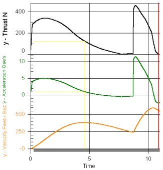
Sample Thrust, Acceleration and Velocity Curves
 |
|
In the example above, the
booster motor has significant thrust through burnout which
simplifies the challenges of staging composite motors and the
sustainer motor would ideally be at full thrust by 1½ seconds
after liftoff. An
Aerotech
White Lightning motor (with a strong igniter, see below) will
take approximately ½ to one second to reach operating pressure
and sustainer ignition should be initiated about one second
after liftoff. The velocity should not be a consideration in
this case since there is little or no coast time. This could be
accomplished by using a timer that detects liftoff and starts
its countdown when the rocket launches. The above curve shows
what happens if sustainer ignition is delayed and that will be
discussed more in a moment.
Igniting the sustainer motor
too soon could make booster-sustainer separation an issue. If
the booster motor is producing significant thrust while the
sustainer motor reaches full thrust, there is a possibility of
booster damage from the sustainer motor blast (which actually
occurred in this case). Remember that most motor data is based
on a small number of test firings and you should expect
variances from motor to motor. Beginning sustainer ignition at
one second after liftoff in the above case provides a buffer for
the variances in motors and allows time for safe
booster-sustainer separation. If the sustainer motor comes up to
operating pressure on the slow end of the scale, the additional
½ second delay does not have a significant impact on velocity.
If the timer cannot be set in
½ second intervals (some timers have one second intervals),
sustainer ignition could be delayed until two seconds after
liftoff. This is now a minimum of one second coast time, ½
second for the timer and a minimum of ½ second for thrust
buildup. Hence the
RockSim
simulation above, an I300T with a one second delay and an I161W.
The velocity has now decreased 20 percent by the time the
sustainer motor has reached full thrust. The velocity is still
sufficient to maintain stability, but the rocket will arc
slightly prior to sustainer ignition and it will take a portion
of the sustainer thrust just to recover the lost velocity. In this example, the booster motor burnout time (as shown on the thrust curve) is an acceptable approximation of the boost phase maximum velocity point. However, it could be unsafe to use a "published" motor burn time without referring to the thrust curve. The differences between the thrust, acceleration and velocity curves in this situation are insignificant, but that may not always be true as shown below. |
|
Sample Thrust, Acceleration and Velocity Curves
 |
|
The booster motor shown above
still has a significant amount of thrust at the maximum velocity
during boost and the thrust slowly decreases over several
seconds. Ignoring the low liftoff acceleration (should be a
minimum of 5.5 g's), this motor still provides challenges as a
booster motor. The major challenge will be what delay to use to
allow a safe booster-sustainer separation. Swapping the booster
and sustainer motors would be a much better option, and the
maximum altitude would be increased. Without a simulation program to produce acceleration and velocity curves, the motor thrust curve will be the main tool and using motors that produce significant thrust until burnout will make the decision easier and more accurate. |
|
BOOSTER-SUSTAINER SEPARATION
The booster and sustainer can be
separated by drag or by some imposed force. Drag separation is
what happens on a single stage rocket when sections fit too
loose and they come apart after motor burnout, usually resulting
in an early deployment of a parachute. If this same method is
used to separate stages, then whatever is used to ignite the
sustainer motor (timer for example) must be mounted in the
sustainer. Physically forcing the booster away from the
sustainer can be as simple as a drag separation by using the
sustainer motor or more complex by adding some device (such as a
small black powder charge) to provide the energy.
Using the sustainer motor to separate
the booster and sustainer is simple and repeatable. One problem
with igniting the sustainer motor prior to booster-sustainer
separation is damage due to the sustainer motor blast hitting
the booster. This problem can be lessened or prevented by using
materials in the booster that will survive the blast. The
booster design must prevent sustainer motor blast from entering
inside the booster and damaging the electronics or recovery
system. Separating the booster and sustainer prior to the sustainer motor reaching full thrust looks more realistic and is aesthetically pleasing to the audience. By adding a device such as a black powder charge, the booster and sustainer can be separated before the sustainer motor ignites. When the stages are separated before the sustainer reaches operating pressure, the rocket will coast for a time. The sustainer motor needs to reach full thrust before the rocket slows and turns away from the desired flight path and toward the ground. A simple method for booster-sustainer separation on a single event timer is to wire the separation charge in parallel with the sustainer igniter. This separates the booster from the sustainer during the time it takes the sustainer motor to reach full thrust. This option retains the option to mount the timer in either the booster or sustainer. Sustainer motors that take a significant amount of time to ignite and reach full operating pressure can be ignited prior to booster separation, even while the booster motor is still burning. In this case a two-event timer is required.
USE CAUTION:
If the timer is mounted in the
booster, the wires from the timer to the igniter should have a
“quick release”. Otherwise the igniter, or sustainer motor, may be
pulled from the sustainer during separation. |
|
SUSTAINER MOTORS The
purpose of the sustainer motor is to achieve, and maintain as
long as possible, the final desired velocity (without delving
into the aerodynamics, this will be just below the transonic
regime for subsonic flight). There will be a wider selection of
motors that can be used in the sustainer, but there are a few
areas that should be considered. A
good rule-of-thumb for sustainer motor sizing is to have a
minimum thrust to weight ratio of 3. If the sustainer motor has
a fast initial thrust build-up the problem of sustainer motor
ignition timing is simplified as discussed above. The
main challenge in sustainer motor selection is igniting the
motor with a limited power source, usually a 9 volt battery. A
faster burning motor is generally easier to ignite while the
slower, longer burning motors are more difficult. An electric
match dipped in pyrogen, as described below, can be very
effective in igniting most motors.
Aesthetically, long burning motors in
the sustainer are pleasing to watch but faster burning motors
will generally produce higher altitude (assuming constant
specific impulse and not exceeding the final desired velocity).
A simulator program will be very useful in matching the booster
and sustainer motors to maximize altitude. |
|
ELECTRONICS
Multi-stage flight requires some means of igniting the sustainer
motor and of deploying the sustainer recovery system.
Other methods of igniting a sustainer motor are available (such
as thermalite), but timers are becoming the preferred choice. A
timer should be able to detect liftoff and preferably would be
adjustable in ½ second intervals. Timers adjustable in one
second intervals are more common and they are certainly
acceptable, they may require more attention to booster and
sustainer motor selection as described above. Whether a single
event timer will be sufficient will depend on the complexity of
the rocket and the method used for booster-sustainer separation.
Location of the timer will be dictated by type of
booster-sustainer separation. If separation occurs prior to
sustainer motor ignition, then the electronics must be mounted
in the sustainer. For
three-stage flights, the timer for third stage ignition should
have a method of confirming second stage ignition. If the second
stage motor does not ignite, the rocket could have a significant
trajectory change (and be pointed at the ground) before the
timer ignites the third stage. Timers that have a "pull switch"
circuit can be used for this purpose. The
sustainer should have an electronic means of deploying its
recovery systems. If the sustainer motor is the only means of
deploying the recovery system and it does not ignite, there will
be no recovery system deployment. A timer can be used as a
backup to motor ejection or as the primary means of deploying
the sustainer recovery system. A two-event timer mounted in the
sustainer could be used for sustainer motor ignition and
recovery system deployment.
Timing for sustainer recovery system deployment is not as
straight forward as for single-stage rockets and timer delays
become increasing difficult to select properly. Predicting the
thrust buildup time for the sustainer motor directly affects
which timer delay to use. The thrust buildup time also affects
maximum altitude, and time to apogee, which must also be
considered in the time delay for recovery system deployment.
Finally, multi-stage rockets reach higher altitudes and the time
for recovery (and therefore drift) is increased if the main
recovery system is deployed at apogee. Electronics, such as an
altimeter or accelerometer, should be used. A multi-stage flight with a two-event sustainer recovery is a complex launch and should not be attempted for the first time all at once. Launch the sustainer as a single-stage rocket, with two-event recovery, until you are comfortable with the recovery technique and the electronics. Then add the booster for a two-stage flight. A set of abbreviated instructions, or checklist, can be a valuable aid in completing all of the steps required for flight preparation. |
|
SUSTAINER MOTOR IGNITERS
Igniters used in staged motors must
be reliable and should not overload the timer power supply.
Electric matches use very little
current to ignite, but on their own they are insufficient to
reliably ignite composite motors. A solution is to dip the
electric match in pyrogen which is easily ignited by an electric
match. The electric match provides the reliable spark while the
pyrogen provides the ignition power. If the motor throat
diameter permits, fold over the top of the electric match before
dipping in pyrogen. For even more starting power, small
slivers of Aerotech Blue Thunder propellant can be ties or taped
to the igniter. |
 |
Electric Match
Igniter. Before and after being dipped in Pyrogen. This igniter is for use in an Aerotech White Lightning motor so the match was not folded over prior to dipping. |
|
If an electric match igniter
will not fit through the nozzle, the igniter may have to be
inserted during motor assembly.
USE
CAUTION -
Because electric matches require so little current, they can be
ignited by static electricity. Do not expose the ends of the
match wires, or wrap the exposed wires of
each
individual match together, until you are at the pad and ready to
hook them up to the launch power supply.
To hold the igniter in place, use a plastic ring cut
from the black powder “container” that comes with the motor. |
|
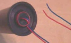
Igniter Installation. This installation has proven successful for all situations. The igniter stays in place and there is no blockage of the motor core or nozzle. Even if the ring is not pulled free, the portion of the igniter in the motor is quickly burned and ejected. Note that the ends of the igniter are not exposed. |
 |
|
|
|
STAGING ROCKET STABILITY
Rocket stability needs to be
confirmed for each stage. Checking the booster-sustainer
combination is usually not overlooked but if the sustainer is
never flown as a single stage rocket, its stability is easy to
forget. The stability of the booster alone should also be
considered. Otherwise, you could find that the booster swaps
ends or tumbles after separation, potentially hitting the
sustainer or fouling the booster recovery system. Placing the
timer for sustainer ignition in the booster coupler or extending
the length of the booster will help increase booster stability. Flow interference from the sustainer fins could cause the booster fins to be ineffective. This would almost certainly cause the booster-sustainer combination to become unstable. This should not be prevalent in existing sounding rocket designs where the sustainer fin design and the booster length allows any flow disturbances over the sustainer fins to smooth out before reaching the booster fins. |
|
RIM-67 Standard Fin Design
The fin design on this sustainer is the probable cause of this booster-sustainer combination being unstable at the end of the boost phase. As the booster-sustainer began to decelerate the airflow over the long sustainer fins "separated" and became turbulent. The booster fins became ineffective in this flow (moving the CP forward) and the rocket became unstable between booster motor burnout and booster-sustainer separation. This project was ultimately abandoned. |
|
Additional nose weight can always be used to move the CG forward and increase stability. However, this technique cancels the main reason for using motor staging - achieving higher altitude. |
|
Copyright© 2014 All Rights Reserved |

