 |
Spaceport Rocketry Association Premier rocketry organization serving the Florida Space Coast since 1973 |
| Gallery |
|
Dual-Event Recovery Information |
|
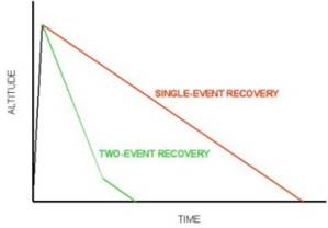
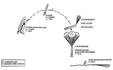
WHY DUAL-EVENT RECOVERY Dual-event recovery is electronic based apogee (drogue) and main recovery. It adds complexity to the rocket, increases the cost, and increases the rocket preparation time. However, these disadvantages are quickly overcome by the desire to decrease recovery time (and therefore drift) as the rocket altitude increases. The Shuttle Solid Rocket Boosters used similar altimeter based recovery and so there’s also the joy of taking another step into real rocket science.
|
|
ROCKET DESIGN
Using a kit made specifically
for dual-event recovery is an excellent way to begin. Follow the
manufacturer instructions and you are well on your way to your
first successful dual-event recovery. I began with a PML Thunder
-N- Lightning. Starting with the sustainer as a single stage I
was able to become comfortable using altimeter recovery. When I
was ready, I already had the booster for the next step,
two-stage flights.
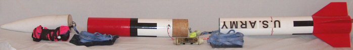
A common dual-event recovery
design is to split a rocket into three sections, with the
sections connected by shock cords. Selection of shock cord
length and width is the same as for single-event recovery. A
good rule-of-thumb for shock cord length is three times the
length of the rocket. Ejection charges controlled by electronics
are used to split the rocket into the appropriate sections to
deploy the drogue recovery system at apogee and the main
recovery system at a predetermined altitude. The center section is further divided to provide access to the electronics and ejection charges during preflight. Once the electronics and ejection charges are installed, the two center sections are secured together for flight.
|
|
DROGUE RECOVERY SYSTEM
The main purpose of the drogue
recovery system is to have a controlled and stable high-speed
descent. The higher the descent rate, the less drift there will
be. However, the descent rate must be low enough for a safe
deployment of the main recovery system without any damage to the
rocket. A good rule-of-thumb for a good drogue descent rate is
50 feet per second.
The drogue recovery system is
normally located in the aft section of the rocket and is
deployed when the drogue (apogee) ejection charge separates the
motor/fin section from the center section. Since the nose cone
is generally lighter than the motor/fin section, the nose cone
(and thus the main recovery system) is less likely to separate
prematurely due to the drogue opening loads. In the event there
is still significant velocity at apogee (arcing flight), having
the motor/fin section separate first limits the possibility of
rocket damage (assuming a long enough harness to dissipate the
energy). Having the drogue recovery system aft and the main
recovery system forward also moves the CG forward, increasing
stability. Rocketry Online's INFOcentral Recovery section has an excellent discussion on drogue sizing. |
|
MAIN RECOVERY SYSTEM
The purpose and design of the main
recovery system does not change for dual-event recovery. The only
additional concern may be the limited room available in smaller
dual-event recovery rockets since some of the airframe is now
being used for the drogue and electronic systems. The main
recovery system is normally installed in the forward section of
the rocket and is deployed when the main ejection charge
separates the nose cone from the center section. If the airframe
space allows, the main and drogue locations can be switched, as
long as the section security and rocket CG are considered as
discussed above. Using the same arrangement on all of your
dual-event recovery rockets will keep rocket (and electronics)
preparation consistent. This will help prevent switching the
drogue and main connections on the altimeter and inadvertently
deploying the main recovery system at apogee.
Rocketry Online's INFOcentral
Recovery section has an
excellent discussion on main parachute sizing. |
|
ELECTRONICS
Electronics that can detect apogee
for drogue deployment and a predetermined altitude for main
recovery system deployment, such as an altimeter or
accelerometer, are required.
A basic altimeter should have an
apogee (drogue) and a main deployment circuit. The main circuit
may have two or more selectable deployment altitudes. The lower
main deployment altitudes reduce the recovery time and drift,
but higher altitudes are required for rockets where the main
recovery system takes longer to fully deploy. Some altimeters
will have a supersonic inhibit delay. Air pressure rapidly
changes as a rocket passes in and out of the transonic and
supersonic regimes. An altimeter will improperly sense these
pressure changes as apogee and deploy the drogue recovery system
at very high speed. The supersonic inhibit delay prevents the
altimeter from using pressure readings for a user selectable
time after liftoff. A good rule-of-thumb is to use this delay
anytime the rocket will exceed 750 feet per second. If the
rocket reaches apogee before the delay time expires, the
altimeter will not deploy the drogue recovery system so this
inhibit should be used cautiously and only when required.
Altimeters will vary on what information they record and how it
is displayed. A few altimeters do not have any altitude
reporting capability while most will report maximum altitude
through light or audio signals. Some "logging" altimeters record
altitude at set time intervals that can be downloaded to your
computer. These options do not affect the operation of the
altimeter and which one you choose will be based on personal
preference and how much you are willing to spend.
An accelerometer does just as its
name implies and senses rocket acceleration. The accelerometer
will differentiate the acceleration to derive velocity and
altitude and it deploys the drogue recovery system at apogee
when it "senses" zero velocity. For accuracy an accelerometer
should have a pressure sensor for main recovery system
deployment, and like the altimeter, there may be two or more
selectable deployment altitudes. This sensor is usually not
activated until after apogee so a supersonic inhibit delay is
not required on an accelerometer. The information available from
an accelerometer allows extensive evaluation of the rocket's
flight from liftoff through touchdown, which can be an excellent
learning tool for the young, and old alike.
Electronics will be designed with
varying power supplies. Some will have built-in, rechargeable
batteries while others will have a battery holder, or power
connection, for a battery. Electronics designed for 9-volt
batteries are very convenient. The 9-volt batteries are readily
available and a fresh battery can easily be used on each flight
(highly recommended!). A fresh 9-volt battery will have ample
power to run the electronics, even with a reasonable delay at
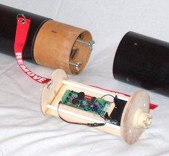
the pad, and still fire two or more electric matches. There are many commercial systems available for mounting electronics. Some are as simple as an electronics bay that slides into a coupler connecting the two center sections. Others, like PML's CPR system, are more complex but offer some advantages. Using the PML CPR system allows electronics to be easily and quickly moved from one rocket to another no matter what the diameter (2 inches and above). The CPR system also makes connecting the two center sections very easy. Whatever installation you choose, make sure that it will hold any electronics that you may obtain taking into consideration the length, width and depth of the electronics with batteries installed. The installation must also protect the electronics against the hot gases from the ejection charges. Even if the electronics are not directly damaged, these gases are corrosive and will damage the electronics over time. |
|
EJECTION CHARGES
Unlike using engine ejection,
dual-event recovery is going to require extra effort in preparing
the ejection charges. The required ejection charge size will
vary based on the airframe space available and they could be
very different for the drogue and main sections. Using a
"standard" amount of black powder could leave one section
under-pressurized, which could fail to deploy the recovery
system, while the other is over-pressurized damaging the rocket.
Take time to determine the correct ejection charge size for each
application.
Rocketry Online's INFOcentral
Recovery section has an
excellent discussion on, and a calculator for, ejection charge
sizing.
The ignition source for the ejection
charge needs to be compatible with the power source for the
electronics. At best, this is typically a 9-volt battery and
electric matches are an excellent choice. USE CAUTION - Because
electric matches require so little current, they can be ignited
by static electricity. Use caution when handling the ejection
charges and electronics with ejection charges installed. Follow
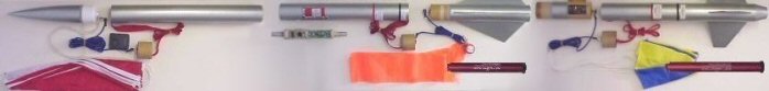
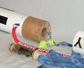
the manufacturer instructions for the electronics. The acceleration of liftoff and drogue opening loads will try to force the black powder out of the ejection charge holders. It is a good habit to build all ejection charges so that the black powder remains securely in contact with the electric match (or whatever ignition source is used). To hold the black powder in contact with the electric match this ejection charge has; a self-adhesive disk over the black powder; fire-resistant wadding to fill in the remaining space; and masking tape to hold the entire assembly together. |
|
BUILDING CONFIDENCE IN THE ELECTRONICS
So what’s holding you back? For most
people, unfamiliarity with the electronics and the added
complexity breeds mistrust. Using a slight modification in the
rocket design provides a way for you to get to know your
electronics without having to depend on them. The drawback, you
will need to modify an existing kit or design with a payload
section and electronics bay (but read on because it’s not
difficult). |
|
ALTERNATE ROCKET DESIGN This design is a simple addition of an electronics bay to an existing motor ejection based kit or design with a payload section. The payload section needs to be long enough for the electronics and a main parachute. My experience has been that this section needs to be at least 18 inches long, but that will vary based on the type electronics used and main parachute size.
The two required modifications are: 1) a shock cord
between the nose cone and upper section, and 2) adding an
electronics bay to the payload section coupler. Two possible
electronics bay modifications are shown below.
This design can be used for
motor ejection only, combined motor and electronic ejection or
electronic ejection only. The motor ejection only option is nice
when recovery time (drift) is not a consideration and you are
not in the mood for a lot of preparation. When you’re
comfortable with the electronic ejection only option, then you
can comfortably move to rocket designs discussed above. The
combined motor and electronic ejection option is where you can
gain that confidence. To gain confidence in your electronics, prepare the alternate design rocket with motor ejection, the main parachute loaded in the motor section and the electronics set up with either simulated or actual ejection charges. The simulated charges would be the resistors (or whatever the manufacturer supplies) installed in the deployment circuits. Do not, ever, directly short a deployment circuit by using a wire. When the electronics activate, the direct connection will damage the electronics. You will know if the electronics worked in-flight if the electronics are providing the proper signals per the manufacturer instructions. By using actual deployment charges, you can add visual feedback in-flight if the electronics are performing as expected. In this case, since the main parachute is loaded in the motor section, the electronic apogee function will act as a backup to the motor ejection. The electronic main circuit will simply deploy the nose cone (and anything you decide to pack in the upper section). When you gain confidence and using actual deployment charges, you can move the main parachute to the upper section and load a drogue recovery system in the motor section. The motor ejection will provide redundancy for the drogue (apogee) deployment. If for some reason the electronics do not work, and the main parachute does not deploy, chances are the rocket will not be a total loss because the motor ejection has deployed the drogue. You can even use a larger drogue initially and decrease its size as you gain confidence. |
|
Copyright© 2014 All Rights Reserved |