 |
Spaceport Rocketry Association Premier rocketry organization serving the Florida Space Coast since 1973 |
| Gallery |
|
Motor Clustering Information |
|
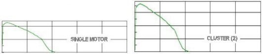
Motor clustering is the use of more than one motor fired at the same time. Clustering adds together the thrust level, and thus the lifting or pushing power, of all the motors used. This makes it a good technique for lifting heavy payloads and large rockets.
|
|
Almost any motor can be used for clustering. Because the thrust
level is multiplied, it is sometimes possible to use long burn
time motors that may not otherwise be recommended. In some
cluster arrangements, all motors are the same; in others, motor
types can be mixed. Two, three, and four motor clusters are
common. More than four should be considered an advanced
technique, because ignition reliability goes down as more motors
are used. The better your igniters and your power supply, the
more reliable your clusters will be.
Motor clustering requires design changes that will affect rocket
stability. Additional motors affect the rocket Center of Gravity
and the additional room to mount them could change the rocket |
|
CLUSTER MOTOR ARRANGEMENT Clusters are often arranged to keep the center of thrust as close to the centerline of the rocket as possible to limit asymmetric thrust in the event an motor does not ignite. The key to any arrangement is keeping the thrust symmetrical. If three motors are arranged in a triangle, all need to have the same thrust curve or the rocket will be pushed off course. In a square cluster of four, it's possible to fly with two sets of two, by putting equal motors on opposite corners. If there is a central motor, the others can be inside the main body as shown in Figure 2, or they can be attached as outboard pods or "strap-ons". The outboard motors can be different from the central one, so long as motors on opposite sides of the centerline are balanced. It's common to put a long-burning, low thrust motor in the center and high-thrust, short burning motors outboard. |
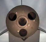 |
Nike - Black Brant Vb
Motor Arrangement. The booster and sustainer have the same motor arrangement. When flown as a two-stage rocket, only the center motor mount in the sustainer is used. This is the booster motor section with a 54mm to 38mm adapter installed in the center position. |
|
Placing motors on fins or otherwise very far from the centerline
is not recommended. If one motor fails to ignite, the rocket
will fly in a high-speed loop. |
|
CLUSTER MOTORS
Unlike staging, clustering is almost
as easy to do with some composite motors as it is with black
powder; but this should still be considered an advanced
technique, if only because a lot of power will be involved. Some
composite propellants are difficult to ignite, and some kinds of
igniters are unsuitable for clustering. In general, the slower,
longer-burning composites (such as Aerotech Blackjack motors)
are more difficult to ignite and less reliable for clustering.
On the other hand, faster burning motors (such as Aerotech Blue
Thunder motors) can be easily clustered if electric matches are
used to ignite them.
Cluster motors are usually mounted in
individual motor mount tubes held in place by custom centering
rings. Whatever method is used, it is important that the spaces
between the tubes are sealed so ejection charge pressure doesn't
leak out. If any motors are not installed (outboards for
example), then those areas must be sealed prior to flight. All
of the motors can have the same delay to reinforce each other,
or some may be "plugged" and do nothing at all after burnout. If
only part of the cluster is used to activate the recovery
system, take extra care to be sure those motors are ignited. It
can be expensive and embarrassing, not to mention dangerous, if
all the motors fire except the one that opens the parachute. |
|
Nike - Black Brant Vb
Sustainer Motor Mounts.
The motor mount and
fin section (right) was designed to slide into the
airframe. This permitted easy access to all areas for
construction.
Motor ejection
charges were not used for recovery system deployment, so
the entire fin section was sealed by the coupler and
bulkhead assembly (center). If the coupler and bulkhead assembly were omitted, only the center motor could have been used for motor ejection. The outboard motors were sealed by the upper centering ring. |
 |
|
CLUSTER MOTOR IGNITERS
Igniters must be wired in parallel,
so that when one igniter burns through, there is still power
flowing through the others. If the igniters are wired in
"series," when one igniter burns, the circuit is broken. Proper
wiring is easily accomplished by wrapping one wire from each
igniter together to form one connection, then wrapping the
remaining wires together to form the second connection.
Igniters used in clustered motors
must be reliable and should not overload the launch power
supply. Delivering all the current that the igniters can consume
is an important aspect of successful clustering of composite
motors. This is especially true where high current igniters are
employed in conventional launch systems. For example, four high
current igniters wired in parallel, such as Firestars, can draw
in excess of 50 amps of current. If your system can't deliver
that kind of power, the results could be the igniters firing
sequentially rather than simultaneously.
Electric matches use very little current to ignite, but on their
own they are insufficient to reliably ignite composite motors. A
solution is to dip the electric match in pyrogen which is easily
ignited by an electric match. The electric match provides the
reliable spark while the pyrogen provides the ignition power. If
the motor throat diameter permits, fold over the top of the
electric match before dipping in pyrogen. For even more starting
power, small slivers of Aerotech Blue Thunder propellant can be
ties or taped to the igniter. |
 |
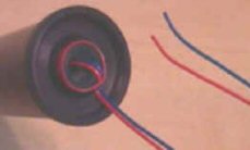
Electric Match
Igniter. Before and after being dipped in Pyrogen. This igniter is for use in an Aerotech White Lightning motor so the match was not folded over prior to dipping. |
|
If an electric
match igniter will not fit through the nozzle, the igniter may
have to be inserted during motor assembly.
USE CAUTION
- Because electric matches require so little current, they can
be ignited by static electricity. Do not expose the ends of the
match wires, or wrap the exposed wires of
each individual match together, until you
are at the pad and ready to hook them up to the launch power
supply. To hold the
igniter where it belongs, bend the igniter over the end of the
nozzle and use a plastic ring to hold it in place. |
|
Igniter Installation. This installation has proven successful for all situations. The igniter stays in place and there is no blockage of the motor core or nozzle. Even if the ring is not pulled free, the portion of the igniter in the motor is quickly burned and ejected. Note that the ends of the igniter are not exposed. |
 |
|
This installation has proven
very useful in cluster launches where a motor has had a slight
delay in ignition. The igniter remained in place, and the launch
power supply remained connected, as the rocket started up the
launch rod. Make sure the LCO knows that it is a cluster launch
so he will hold the ignition button until the rocket is well
clear of the launch rod.
Another method to keep the
igniter positioned in the motor is with string or carpet thread
during motor assembly. Tie the string/thread to the igniter
below the pyrogen and secure it between the top propellant slug
and the top of the motor. (Between the top propellant grain and
the forward insulator for AeroTech motors.) This will hold the
igniter in the top of the motor. Upon ignition the string/thread
will burn so that the igniter wires can exit the motor.
Thermalite, if available, can be used in place of string/thread,
and will assist with motor ignition. |
|
CLUSTER ROCKET STABILITY
Multiple motors at the rear end of the rocket concentrate weight
where it is least wanted and shifts the Center of Gravity (CG)
aft. Cluster rockets often need large fins to counteract this.
Be sure to test the stability of a new design with the heaviest
motors you intend to use in it.
A larger diameter airframe is
required to mount motor clusters. If the rocket length is not
increased the length to diameter ratio is decreased. This has a
destabilizing effect on the rocket.
Outboard motor pods or strap-ons
increase the area at the aft end of the rocket. The effect on
the rocket Center of Pressure (CP) will vary depending on the
total design. If not already accomplished by a manufacturer or
designer, a CP/stability prediction program should be used to
test the design. Additional nose weight can always be used to move the CG forward and increase stability. However, this technique cancels the main reason for using an motor cluster - lifting heavy payloads and large rockets. |
|
MOTOR FAILURE(S) ON LIFTOFF The possibility of motor failure(s) on liftoff must be considered when launching with an motor cluster. The risks can be minimized by ensuring that a safe liftoff and recovery will still occur even with the motor failure(s). This can be accomplished by; using motors that ignite reliably and reach operating pressure quickly; ensuring that a minimum safe velocity will be reached prior to the end of the launch rod with motor failure(s); using a longer launch rod to provide more acceleration time; and by using a reduced wind limit which allows a lower minimum safe velocity. |
|
Copyright© 2014 All Rights Reserved |